Ohio State University Chiller Plant
PROJECT OVERVIEW
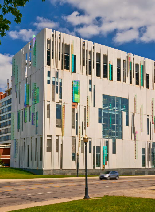
Recent trends in chiller plant design that have been to use eye-catching enclosures, often glass boxes, to allow mechanical systems to be visible from outside. However, this presents the problem of cooling the chiller plant. At Ohio State University in Columbus, Ohio, a new ten-story plant uses precast concrete panels with a series of openings that allow a view inside, while keeping the interior temperature consistent and the energy use regulated.
The plant building is more than just a concrete box with openings, however. Conceived as a “House for Energy,” the envelope showcases the energy-efficient chiller equipment inside and records the sun’s energy on the exterior.
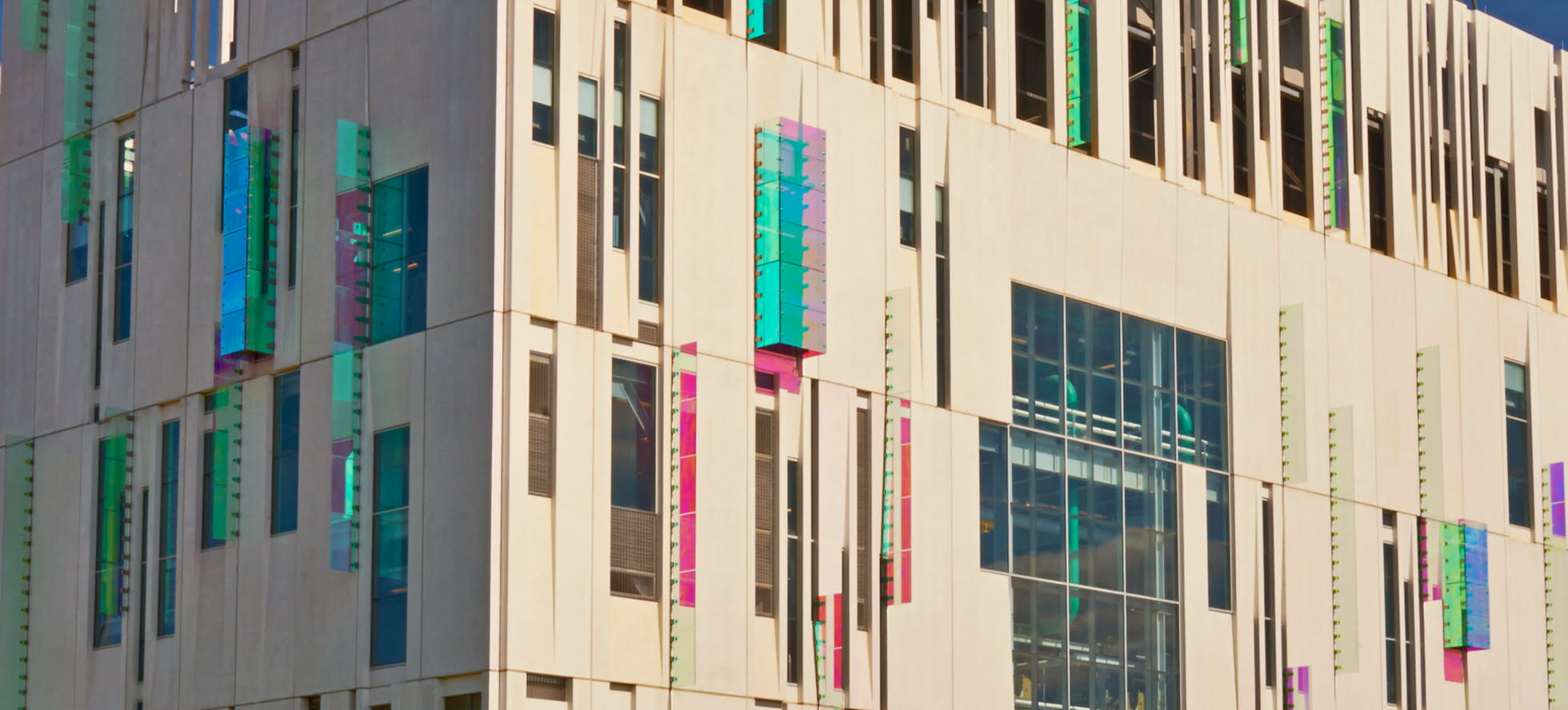
The LEED Silver Certified building features a high-polish finish and “fins” of diachronic glass that cast colored light rays across the concrete surface. The result is a dynamic façade that changes with the time of day, season, and location of the observer.
The chiller housed at the new plant facility provides chilled water production and distribution to the medical center area of the campus. The plant encloses the equipment used to maintain 12,500 tons of chilled water, with a plan to increase that capacity to 30,000 tons. Emergency power installed at the plant increases the reliability of the water production and distribution in the event of a power outage.
Project Details
- Owner: Ohio State University
- Architect: Champlin Architecture
- Engineer of Record: Shelley Metz Baumann Hawk
- General Contractor: Whiting-Turner Contracting Company
Awards
- PCI 2014 Best Custom Solution
Key Project Attributes
-
The LEED Silver Certified building features a high-polish finish and “fins” of diachronic glass that cast colored light rays across the concrete surface. The result is a dynamic façade that changes with the time of day, season, and location of the observer.
-
Sustainability was a key factor in the design of the new chiller plant.
-
The predominant materials on the project are precast concrete, cast-in-place concrete, and steel. Concrete aggregates were locally sourced to reduce embodied energy
Aesthetics
With a high sheen gloss finish, large glazed openings strategically placed to identify the function of the building, and the glass fins in the joints, the precast concrete panels create a unique building that is functional while adding an aesthetic dimension to the highly visible site on campus. Using such varied components required a commitment from all parties to utilize Building Information Modeling (BIM) and 3D modeling to facilitate coordination of all the building elements.
The precast concrete 3D model required a very high level of detail to identify and resolve conflicts between the structural steel frame and precast cladding. Over one hundred connection attachments were pre-attached to the structural steel frame as it was fabricated, saving time during the erection of the structure.
Perfect Assistant
The architectural firms worked closely with the precast producer during the early design stage in developing the over 200 panels created for the building in which there were only 11 different panel types. According to designer Eric C. Martin, AIA, principal from Ross Barney Architects, in Chicago, “By using such a small number of panel types, a significant reduction in precast cost was realized; because the manufacturer was able to utilize these forms multiple times, in lieu of constructing new forms. The design team also wanted to design the largest size panels in order to accelerate the installation process. Transportation criteria dictated the final panel sizes. The size of the panels are 9’-0” x 30’-0”, with the top panels being 35’-0” tall to enclose the cooling towers. High Concrete Group’s involvement during the design was key to the success of the precast work on the project.”
Additionally, the precast concrete model perfected the process to attach the glass “fins” to the structure. Each one of the several dozen fins is made up of multiple sections of laminated, colored glass. The glass sections were attached via brackets that fit into slots on the edge of the precast panel. The glass was pre-drilled for bolts which would then attach to the brackets, therefore the placement of the brackets and the slots had to be very precise. Only one out of over 500 slots was in the wrong place on the concrete panels.
Fins
At the beginning stages of the development of the fin design, the intent was to locate the connection in the joints between the precast wall panels. The structural analysis of the precast panels determined that there would be too much movement in the system, and the connecting bracket and the glass would be crushed.
The design team then proceeded to develop the current bracket connection. To avoid increasing the panel joint width and accommodate the movement between the panels and the thickness of the stainless steel plates for the brackets, the edges of the precast panels were notched to receive the fin’s brackets. The frame, to which the brackets attach, was designed so installation could occur from within the building, and after installation of the precast panels. This technique contributed to worker safety and benefited the construction schedule. The bracket has an angled receiver to hold the glass in place and to prevent rotation of the unit that would occur with only one bolt.
To enhance the colors that radiate from the diachronic fins, the precast concrete panels were polished to high gloss sheen. The polishing process is the same process used for concrete floor slabs in which diamond pads are used for grinding and polishing. Some surfaces were light acid-etched. The precaster created several mock-up panels in order to get the polished finish to a level that was acceptable to the owner and the design team.
Another benefit of polishing the concrete panels was to provide a maintenance free, durable surface that would minimize staining and streaks. The panel back finish was a one-pass hand steel trowel.
Sustainability
This project overall is a testament to the value of 3D modeling and BIM, as well as an excellent example of the versatility of precast concrete. Achieving the level of coordination and resolution of conflicts without the BIM technology would be virtually impossible. Additionally, the vision of using precast concrete in a very different way created a stimulating focal point for this practical and necessary campus building. By using precast concrete the building is visually engaging and completely practical.
Sustainability was a key factor in the design of the new chiller plant. This project is unusual in the sense that it is not designed for human occupants—the building houses chiller equipment. Because of this, conventional sustainable strategies needed to be rethought. Opportunities for sustainable design were in the project siting, water efficiency, and use of sustainable materials rather than the typical emphasis on the energy efficiency of a project’s envelope, lighting, or HVAC system. The energy-efficient chiller equipment which the project houses, however, contributes to the energy conservation of the medical campus facilities that it serves.
The predominant materials on the project are precast concrete, cast-in-place concrete, and steel. Concrete aggregates were locally sourced to reduce embodied energy. The project received two LEED points for both Recycled Content and Regional Materials, in addition to all available points for low-emitting materials.
ELEVATE YOUR PRECAST DESIGN.
Have a question about our precast design options? That's what we are here for. Reach out to our team of precast design engineers with any questions or details about your project and we will get back to you.

